|
Frequently Asked Questions
1. X-Ray Systems
What are the main components of a typical digital x-ray system?
Which x-ray system components does Rad-icon supply?
Are there different sizes and/or different types of x-ray sources?
How much x-ray power do I need?
What are the tradeoffs between spot size, magnification and resolution?
What are the tradeoffs between source power, source-to-detector distance and exposure time?
2. Cameras
What is the difference between an x-ray detector and a camera?
How do I choose a digital x-ray camera?
What's the difference between a framing camera and a snap-shot camera?
How are frame rate, exposure time and integration time related?
How is integration time measured in the Shad-o-Box camera?
Can frames be averaged to facilitate a longer exposure?
What is the difference between a standard camera and an EV series camera?
3. Frame Grabbers, Imaging & Software
What type of frame grabber do I need for a Shad-o-Box camera?
How do you control the frame rate with the PXD1000 frame grabber?
How can I use integration times longer than 6700 ms?
What kind of image correction techniques should I use to improve image quality?
How do I open ShadoCam images with another application?
1. X-Ray Systems
What are the main components of a typical digital x-ray system?
- X-ray source
- Digital x-ray camera
- Computer with interface electronics
- Capture software
- Analysis software
- Radiation enclosure
- Sample holder or stage
- Power supplies & cables
[Back to Top]
Which x-ray system components does Rad-icon supply?
Rad-icon Imaging Corp. manufactures x-ray detectors and digital x-ray cameras. We can also supply third-party interface electronics (i.e. a frame grabber), cables, capture software (ShadoCam) and, of course, a power supply with our cameras.
[Back to Top]
Are there different sizes and/or different types of x-ray sources?
X-ray sources are rated by power and by focal spot size. The power is the product of the beam current and the cathode to anode voltage. It determines the maximum x-ray energy (kVp) and the maximum x-ray flux (i.e. dose rate) you can obtain from the tube. The focal spot is the region of the anode that emits the x-rays. The spot size depends on the target material and the power dissipated by the tube. In general, higher tube power requires a larger spot size.
Sources have power ratings ranging from a few watts to many kilowatts. No hard fast definition exists, but a few rules of thumb are used to loosely describe ranges of source types. Tubes with spot sizes larger than 1 x 1 mm are referred to as conventional x-ray sources. Tubes with 0.5 x 0.5 mm down to 50 micron diameter are referred to as fine-focus tubes. Sources with spot sizes of 50 micron diameter or less are called micro-focus tubes. Tubes with spot sizes smaller than 1 micron are beginning to appear and they are called nano-focus tubes.
[Back to Top]
How much x-ray power do I need?
The maximum x-ray energy you need is determined by your sample. Thinner, low-density materials (e.g. plastics) require less x-ray energy than, for example, metals or very thick parts. You also want to make sure that your source has sufficient power to provide enough x-ray flux to give you a useful image signal-to-noise ratio.
As a rule of thumb, materials such as plastic or circuit boards are typically imaged at 50-70 kVp (kVp = peak x-ray energy; i.e. your source voltage setting). Metals may require more energy, up to 120-160 kVp for 5-10 mm thick steel plates. Most systems require 0.5-1.0 mA of source current to obtain good image quality, although you can get by with less current by lowering the source-to-detector distance (SDD) or by increasing the exposure time. The image signal-to-noise ratio (SNR) can also be improved though frame averaging.
[Back to Top]
What are the tradeoffs between spot size, magnification and resolution?
The combination of focal spot size and magnification determines the theoretical maximum resolution in the x-ray image. The finite spot size of the x-ray source creates a penumbra around the edges of the x-ray shadow, much like the sun casting a shadow of your hand. A larger spot size and a longer object-to-detector distance (ODD) both increase the penumbra and thus the minimum feature size detectable at the image plane.
The geometric magnification factor is given by the ratio of the source-to-detector distance (SDD) to the source-to-object distance (SOD). The minimum feature size is calculated by multiplying the focal spot size by the ratio of the ODD to SOD. The camera resolution (pixel size and scintillator) needs to be matched to these parameters in order to be able to image the required features.
[Back to Top]
What are the tradeoffs between source power, source-to-detector distance and exposure time?
The x-ray flux follows an inverse square law: doubling the source-to-detector distance reduces the flux per unit area by a factor of four. This can be compensated by increasing the source current or the exposure time. Detector signal also increases with x-ray energy, but using too high a kVp setting can reduce image contrast.
[Back to Top]
2. Cameras
What is the difference between an x-ray detector and a camera?
Our x-ray detector modules (i.e. the RadEye product line) consist of a CMOS sensor packaged together with a scintillator and a protective cover. This is analogous to the CCD chip inside a CCD camera. You need to supply power, a reference voltage and clock signals, and then digitize the analog output signal(s) for acquisition into a PC.
Our digital x-ray cameras (the Shad-o-Box & Shad-o-Snap product lines) combine a detector module along with camera electronics and shielding to provide a compact, easy-to-use imaging system. Simply connect a power supply and a data cable (frame grabber or USB), and you’re set to start acquiring images.
[Back to Top]
How do I choose a digital x-ray camera?
There are many camera specs that are important to the end user, including size, resolution, sensitivity, frame rate, ease-of-use, cost etc. Different camera technologies often excel at different applications. For a more detailed comparison of various x-ray sensor technologies such as amorphous silicon, CCDs and CMOS sensors, please see our white paper titled “Large Area Digital X-ray Specific Imagers” (application note AN02).
A basic approach to choosing a digital x-ray camera starts with the geometry of the x-ray imaging system: what is the image size that I need, and what is the resolution? The answer to these questions often narrows the choices to a specific range of detector area and pixel size. This also leads us to the next question: do I need magnification? If the pixel size of a certain detector is too large for the sought-after image detail, a (more expensive) microfocus source along with geometric magnification can often achieve the required performance. However, keep in mind that with magnification you most likely also need a larger detector area. The total number of pixels in the detector may be a better spec to consider.
Speaking of x-ray sources, what x-ray energy (kVp) do I need to image my parts? Detectors are often rated for a certain energy range, and the detector lifetime is usually a function of both dose and energy.
Other questions to consider include: Do I need to image many parts in rapid succession, or do I take one image at a time? Do I need frame averaging? What kind of PC interface and software do I need? Do I need a portable system or a stationary installation? Are there any special triggering requirements? And, last but not least, how much money am I willing to spend?
[Back to Top]
What's the difference between a framing camera and a snap-shot camera?
A framing camera is used to take continuous video, often at 25 or 30 Hz like a video camera, but also at slower frame rates. The Shad-o-Box is a framing camera. A snap-shot camera, on the other hand, takes one picture at a time, much like a traditional “point-and-shoot” photography camera. The image is stored in the camera and can be downloaded to a PC after the image acquisition is finished. The Shad-o-Snap is a snap-shot camera. Note that a higher frame rate in a framing camera also means a shorter exposure time for each frame, which requires a higher source current to keep the SNR constant.
[Back to Top]
How are frame rate, exposure time and integration time related?
With continuous x-rays (i.e. x-rays are on all the time) the exposure time is simply the inverse of the frame rate. For example, if the camera is running at two frames per second, the exposure time for each frame is 500 ms. On the other hand, if a pulsed source or a shutter is used, then the exposure time is determined by the length of time that x-rays are incident on the camera. This is typically independent of the frame rate. The integration time is the number of seconds that the photodiodes in the sensor array collect charge, which is always the inverse of the frame rate.
[Back to Top]
How is integration time measured in the Shad-o-Box camera?
The Shad-o-Box camera (or, more specifically, the RadEye sensor inside the camera) uses what is often called a “rolling shutter”. The image is scanned one row at a time, starting at the top of the sensor. The signal charge collected in the photodiodes in each pixel is reset as each row is scanned. Because of the sequential nature of the readout, this means that row 1 is reset a few tenths of milliseconds before row 2, which in turn is reset before row 3 etc. The whole process of reading an entire image typically takes a few hundred milliseconds. When the last row is scanned, the camera can either start over again with the first row, or wait a certain amount of time before reading the next image.
Because the photodiodes in the RadEye sensor are always collecting charge, the integration time is simply the number of seconds between one frame readout and the next. Because the delay from the start of the frame readout is constant (but different) for each row, the integration time is also the same for each row. However, since each row has a slightly different integration window (or phase), this can lead to image artifacts if the exposure conditions change before the image readout is complete.
[Back to Top]
Can frames be averaged to facilitate a longer exposure?
Yes, multiple frames can be averaged to improve the SNR and increase the effective exposure time. Often this is easier than extending the exposure time, because it prevents the detector from saturating or collecting too much dark current. The improvement in SNR is proportional to the square root of the number of frames averaged.
[Back to Top]
What is the difference between a standard camera and an EV series camera?
The simple answer is that our standard detectors are rated for the 10-50 kV energy range, whereas the EV series detectors are rated up to 160 kV. However, the actual situation is a bit more complicated. All x-ray detectors deteriorate over time as a function of the accumulated x-ray dose to the detector. The higher the x-ray energy, the faster the detector deteriorates. Our EV detectors contain additional shielding to make them more resistant to radiation damage, and thus they feature a longer lifetime and are able to withstand higher x-ray energies.
Please take a look at our application notes AN06 “Detector Lifetime and Radiation Damage” and AN07 “Scintillator Options for Shad-o-Box Cameras” for more detailed information regarding the performance differences between standard and EV series devices.
[Back to Top]
3. Frame Grabbers, Imaging & Software
What type of frame grabber do I need for a Shad-o-Box camera?
The Shad-o-Box cameras will work with most standard digital frame grabbers. The frame grabber interface consists of 16 data lines, three timing outputs (pixel clock, hor. sync and vertical sync), a strobe input and four control I/O lines. Both RS-422 and LVDS versions of the cameras are available. A custom cable is required for most frame grabbers, although some frame grabbers that use the 68-pin AIA interface may work with just a simple SCSI cable.
[Back to Top]
How do you control the frame rate with the PXD1000 frame grabber?
The PXD1000 frame grabber uses a “.cam” file to load camera-specific settings. The easiest way to change the frame rate is to modify the camera configuration structure and reload it. This can be done with the following code segment:
CAMERA_TYPE* camType;
char camFile[]="SB1024PX.CAM";
camType = pxd.LoadConfig(camFile)
camType->frame_period = (float)0.5; // set STROBE0 to new frame period
pxd.SetCameraConfig(hFG, camType);
pxd.ContinuousStrobes(hFG, TRUE); // turn on camera frame sync
[Back to Top]
How can I use integration times longer than 6700 ms?
There is no upper limit on the integration times used with the Shad-o-Box camera itself. However, the integration time is usually controlled by a counter on the frame grabber board, which typically has a limit of a few seconds before it rolls over. For the PXD1000 frame grabber this limit is 6700 ms.
In order to use longer integration times, you need to either connect to the external trigger input on the camera, or activate the frame grabber trigger separately via custom software (this latter approach is beyond the scope of this tutorial). Simply connect a cable to the “Ext. Sync” SMA input on the camera front panel and supply a TTL or 5 V pulse each time you want to read out the sensor. The pulse length should be between 10 and 100 ms. The period between pulses determines the integration time.
Remember that you need to disable the trigger from the frame grabber when doing this – otherwise the two signals will compete with each other. You can also use the same technique with our Shad-o-Snap cameras, where the integration time is internally limited to 33.5 seconds. Placing the camera into “Mode 1” allows you to control the integration time through the external trigger input. Please refer to your camera hardware manual and to our application note AN04 “Imaging with Pulsed X-Ray Sources” for more information on camera timing.
[Back to Top]
What kind of image correction techniques should I use to improve image quality?
X-Ray image sensors typically require some post-processing of the raw image data in order to optimize the image quality obtained from the detector. Rad-icon’s sensors are no exception. Although it is possible to acquire usable images directly from a Shad-o-Box or Shad-o-Snap camera, one can achieve dramatic improvements in image quality by applying a few simple correction techniques. The three basic calibration methods are Offset Correction, Gain Correction and Pixel Correction.
Offset correction is simply the process of subtracting a Dark Image or Offset Image from the image that is to be corrected. The Offset Image is usually an average of 4-16 frames taken without x-rays (i.e. “in the dark”). It contains the electronics offset as well as a small amount of sensor fixed pattern offset (typically evidenced by faint vertical stripes in the image) and dark current. Because the dark current component can vary over time and with temperature, it is important to refresh the Offset Image at regular intervals. Depending on the application, this could mean as frequently as every few minutes, but typically at least once an hour. You also need to acquire a new Offset Image whenever the sensor integration time changes.
Gain correction normalizes an image for variations in sensor response and x-ray intensity. This includes pixel-to-pixel variations in gain, local variations (e.g. dark spots), as well as image-wide gradients. A Flat Field or Gain Image is used to measure the exact response for each pixel. The Gain Image is typically averaged over 4-16 frames to reduce x-ray shot noise, and should be taken with an unobstructed beam. For best results, the average signal level in the Gain Image should be similar to the average signal level of the image you want to correct. Usually that means that you have to turn down the x-ray power slightly to account for the absorption in the final image. The Gain Image should always be offset-corrected. Because the sensor response is inherently stable, it is not necessary to refresh the Gain Image every time a new Offset Image is taken, but you may need to update the Gain Image if the imaging conditions (i.e. the average signal level) change.
Finally, pixel correction is used to correct for dead or missing pixels in the image. A Pixel Map identifies every bad pixel in the sensor. The Pixel Map is typically generated by the manufacturer during final testing and ships with the camera. It consists of simple text-based entries identifying defective pixels, rows and columns. Although the Pixel Map for a particular detector rarely changes, it is possible to edit it or even generate a new Pixel Map in the field. For additional information on pixel correction, please refer to our application note AN03 “Guide to Image Quality and Pixel Correction Methods”.
The following figures illustrate the effectiveness of image correction. The first picture shows a raw image acquired with a Shad-o-Box camera. The second and third pictures show the same image with offset correction and then gain correction applied. The last picture adds pixel correction to complete the calibration sequence. All four images are displayed using the same contrast and brightness settings.
|
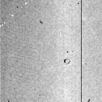
raw image
|
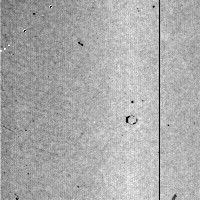
+ offset correction
|
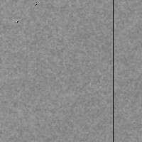
+ gain correction
|

+ pixel correction
|
|
Rad-icon’s ShadoCam software makes using image corrections as easy as pushing a button. Use the functions in the Calibration Menu to manage the correction images and the Pixel Map. Corrections are automatically applied to new images acquired from the camera. If you are writing your own code, our ShadoCam Imaging Library packages the same calibration functions in an easy-to-use C library. Please take a look at the ShadoCam help file and the SIL User’s Manual for further details.
[Back to Top]
How do I open ShadoCam images with another application?
ShadoCam images use the “raw” file format which consists of a signed, 16-bit integer value for each pixel. There is no image header. We use signed integers (values ranging from -32768 to 32767) rather than unsigned integers (values ranging from 0 to 65535) to allow for negative pixel values, for example due to the random noise in a dark part of the image. The files are stored in the “Big-Endian” format (also known as the non-Intel, Motorola or Mac byte order), which means the high byte precedes the low byte in each pixel value stored in the file.
To open a ShadoCam image in another application such as Photoshop, first make sure that your software can open or import 16-bit images. There should be a dialog in which you specify the image parameters such as the number of rows and columns and the pixel type. Enter the image size of your camera, and the pixel parameters described above. Note that many applications immediately map the 16-bit image into an 8-bit gray scale, which means that you may lose some of the details in the process.
You can also save ShadoCam images as BMP, TIF or JPG files using the “Export” command in the File Menu. Please refer to the ShadoCam help file for more details.
[Back to Top]
Got a suggestion for a new topic? Please
|